
RV Tech Schematics
RV Tech Schematics Thor Motor Coach Technical Systems & Wiring Pinouts
● SCHEMATIC REPO 12V DC / 120V AC SPLIT-PHASE PRECISION CIRCUITS / WFCO

Thor Motor Coach Wiring Diagrams & 12V/120V Electrical Pinouts

Thor Motor Coach electrical systems utilize dual 12-volt DC house batteries paired with a 30-amp or 50-amp 120-volt AC distribution panel and automatic transfer switch. Factory wiring schematics isolate chassis ignition circuits from auxiliary coach living loads through a continuous-duty battery isolation manager (BIM).

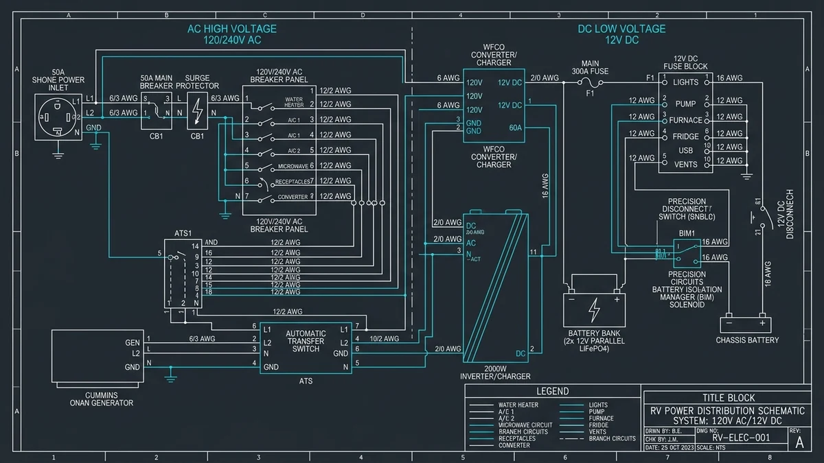
Thor Motor Coach 120V AC and 12V DC Electrical System CAD Schematic Blueprint
High-precision CAD schematic blueprint of Thor Motor Coach 120V AC Automatic Transfer Switch, 50A shore power inlet, BIM 225 solenoid, and DC distribution panel.
PINOUT TRACE / SCHEMATIC BUS

Interactive High-Contrast Vector Pinout Diagram & Color-Coded Terminal Trace

Active Terminal SHORE L1 IN (120V)
Wire Gauge 6 AWG Black
Circuit Status VERIFIED
⚡ VECTOR CIRCUIT TRACE (WEAPON 1) Click any terminal button or SVG wire to dynamically highlight circuit run
50A SHORE INLET ONAN GENERATOR 120V / 240V FEEDS AUTOMATIC TRANSFER SWITCH SOUTHWIRE 41260 / PD52 BIM 160/225 SOLENOID MAIN LOAD CENTER WFCO BREAKER PANEL 12V DC FUSE BUS
ATS-SHORE-L1

SHORE L1 IN

120V AC
Subsystem Unit: Automatic Transfer Switch (ATS)
Wire Gauge (AWG): 6 AWG (50A) / 10 AWG (30A)
Factory Wire Color: Black
Circuit Max Current: 50 Amps

Diagnostic Function & Path

Primary 120V AC Line 1 conductor delivering utility shore power through transfer switch contactor relay to main breaker.

OEM Terminal Torque Spec: 45 lb-in
VECTOR BLUEPRINT & CIRCUIT TRACE

Thor Motor Coach 12V DC & 120V AC Electrical Architecture Blueprint

Interactive 2D vector schematic with component telemetry, wiring trace highlighters, and service tolerances.

SYSTEM: THOR RV BUS X: 22% | Y: 32% [CALIBRATED]
THOR MOTOR COACH E-450 / F-53 BULKHEAD ENCLOSURE
COMPONENT TELEMETRY

Automatic Transfer Switch (ATS 50A/30A)

OEM ELECTRICAL SPEC 120V/240V AC 50A Dual Contactor
TORQUE TOLERANCE 3.5 Nm (31 in-lbs) Lug Terminals
CRITICAL FAULT SYMPTOM

Generator runs with AC output, but no power inside coach (welded contactor or blown delay coil)

ENGINEERING PROTOCOL

Prioritizes generator AC over shore cord with 20-30 second time-delay coil to allow engine RPM stabilization.

HIGH-VOLTAGE ELECTRICAL SAFETY WARNING

DISCLAIMER: High-voltage 120V/240V AC split-phase electrical servicing carries severe risk of electrocution, arc flash, and catastrophic fire. Always disconnect shore power pedestals, disable onboard Cummins Onan generators, trip DC battery disconnect switches, and isolate solar arrays prior to opening transfer switch covers or distribution panels. Work must comply with NEC Article 551 and NFPA 1192 standards. Consult a certified RVDA/RVIA technician.

STATUTORY MODEL ABYC E-11 AC & DC Electrical Systems on Boats and RVs & NEC Article 551

Direct Current Energy & Solar Array Capacity Formula

C_bank (Ah) = (E_daily (Wh) × D_autonomy) / (V_sys × DoD)
Notation: Nominal Bank Ah = (Daily Wh * Autonomy Days) / (System Volts * Depth of Discharge); Solar Watts = (Daily Wh * 1.25) / Peak Sun Hours

Variable Definition & Units

E_daily
Daily Coach Load [Wh]

Aggregate 24-hour electrical energy consumption of all 12V DC and inverted 120V AC devices.

V_sys
System DC Voltage [V]

Nominal coach direct-current bus voltage (12V DC nominal or 24V DC auxiliary).

DoD
Depth of Discharge [Ratio]

Maximum recommended battery discharge limit (85% for LiFePO4, 50% for AGM/Flooded Lead-Acid).

D_autonomy
Autonomy Reserve [Days]

Target boondocking duration supported without alternator, generator, or solar input.

Calibrated Example:

For 2,400 Wh daily demand at 12V DC with lithium (85% DoD) for 1.0 day: Bank = (2,400 * 1.0) / (12 * 0.85) = 235.3 Ah nominal capacity. Solar = (2,400 * 1.25) / 4.5 = 667 Watts.

TOOL-02 / ENERGY ARCHITECTURE

12V DC Battery Bank & Solar Inverter Sizing Engine

12V compressor fridge (~1200 Wh) + furnace fan (~400 Wh) + inverter & lights (~800 Wh).
1.0 Day
1.0 Day 2.0 Days (Weekend) 5.0 Days (Storm Buffer)
Required Nominal Battery Bank
235.3 Ah
At 85% Depth of Discharge
Daily Usable Amp-Hours
200.0 Ah
Net 12V DC consumption
Recommended Rooftop Solar
667 Watts
Based on 4.5 peak sun hours
Inverter Continuous Rating
2000 Watts
Pure Sine Wave standard

Electrical Balance & Charger Profile

  • Converter Profile: Lithium profile requires 14.4V - 14.6V constant voltage bulk charge.
  • BIM Compatibility: Standard Precision Circuits BIM must be upgraded to Li-BIM 225.
EMERGENCY FIELD REFERENCE

Thor RV Electrical & ATS Glovebox Card (4"×6")

Critical Fuse & Wire Gauge Ratings

Circuit / System Min Gauge Fuse / Breaker
50A 120/240V AC Shore Feed 6 AWG Cu 50A Double Pole
30A 120V AC Shore Feed 10 AWG Cu 30A Single Pole
2,000W Inverter DC Input 2/0 AWG 250A Class T Fuse
1,000W Inverter DC Input 2 AWG 150A Class T / ANL
12V DC Shurflo Water Pump 14 AWG 15A ATO/ATC Fuse
Hydraulic Leveling & Slide-outs 4 AWG 50A-80A Auto-Reset

ATS Emergency Triage & Bypass Protocol

  1. Isolate All Power: Disconnect shore power cord from campground pedestal. Switch Cummins Onan generator start switch to OFF.
  2. Verify Zero Voltage: Test L1, L2, and Neutral with a calibrated non-contact voltage tester before opening ATS enclosure.
  3. Chatter Diagnosis: Contactor buzzing/chatter occurs when line voltage drops below 102V AC. Do not force contactor under load.
  4. Terminal Torque Spec: Inspect mechanical set-screw lugs for loose strands. Torque all line and load lugs to exactly 45 lb-in.
  5. Emergency Contactor Locking: If the transfer switch circuit board fails in the field, mechanically lock contactor ONLY after confirming total disconnection from secondary power source.
Source: RV Tech Schematics Independent Diagnostic Hub Standard: NEC Art. 551 / NFPA 1192

Automatic Transfer Switch (ATS) Diagnostics & Failure Modes

The Automatic Transfer Switch—predominantly the Progressive Dynamics PD52 or Southwire 41260 in Thor motorhomes—safeguards onboard appliances by arbitrating power priority between the 50-amp shore utility power cord and the Cummins Onan generator. By engineering design, generator power takes mechanical priority. When the Onan generator starts and reaches governed frequency (60 Hz at 3,600 RPM for 2-pole units or 1,800 RPM for commercial 4-pole diesels), an internal printed circuit board measures voltage on both L1 and L2 lines before triggering the magnetic contactor coil following a 20-to-30-second delay.

120/240V 50A Split-Phase Feed Dual 120V legs out-of-phase delivering 12,000 watts total capacity.
13.3V / 12.6V BIM Voltage Logic Automated alternator charging duty cycle prevents stator burnout.
14.4V - 14.6V LiFePO4 Bulk Charge Mandatory constant-voltage threshold for cell balancing.

Contactor chatter—characterized by a rapid, loud clicking or buzzing from the ATS enclosure—stems from insufficient coil pull-in voltage. If shore pedestal voltage sags below 102V AC under peak summer air-conditioning loads, the electromagnetic coil lacks sufficient flux to hold the contactor plates firmly closed against internal spring tension. Sustained chatter causes intense electrical arcing across silver-cadmium contacts, carbon pitting, and premature contact welding. Technicians must torque terminal mechanical lugs to exactly 45 lb-in using a calibrated insulated torque screwdriver.

Precision Circuits BIM 160, LiFePO4 Lithium & Voltage Drop Calculations

Thor motorhomes connect the engine alternator to the house living batteries using the Precision Circuits Battery Isolation Manager (BIM 160 on AGM/lead-acid models, Li-BIM 225 on factory lithium packages). The unit features micro-controller logic that continuously monitors chassis battery voltage on Stud A and coach house voltage on Stud B.

During alternator charging, the Li-BIM 225 enforces a protective duty cycle: 15 minutes of continuous charge connection followed by 20 minutes of complete separation. This duty cycle prevents the high acceptance rate of low-impedance LiFePO4 cells from drawing excessive continuous current that would overheat the Ford or Freightliner alternator stator.

Proper cable conductor sizing is critical: to prevent excessive voltage drop on 12V DC high-current circuits, the voltage drop must not exceed 3% under continuous load per ABYC E-11 standards. For a 2,000-watt pure sine wave inverter pulling 170 amps over a 10-foot run, 2/0 AWG or 4/0 AWG pure copper cable is required. Under Peukert's law, while traditional flooded lead-acid batteries exhibit an exponent (k ≈ 1.25) causing drastic capacity loss under high inverter loads, modern LiFePO4 cells maintain a nearly ideal Peukert coefficient (k ≈ 1.04), delivering near 100% rated amp-hour capacity regardless of discharge rate.

To diagnose macerator pump electrical circuits, review the Thor RV plumbing and holding tank monitoring systems. For generator oil specifications and electrical inspection schedules, consult the seasonal RV maintenance schedule and roof specs, or return to the master Thor RV technical specifications hub.

Frequently Answered Questions About Thor RV Electrical Systems

How does the Thor Battery Isolation Manager (BIM 160/225) operate?

The Precision Circuits BIM isolates the chassis battery from house batteries to prevent starting discharge. During alternator operation, it senses chassis voltage (>13.3V) and house voltage (<12.6V), connecting them in a duty cycle of 15 minutes on and 20 minutes off to prevent alternator stator overheating.

Why does my automatic transfer switch chatter or hum?

Contactor chatter in an ATS occurs due to shore pedestal low voltage (<102V AC), loose terminal screws causing high resistance, or failing internal time-delay relay coils. Never lubricate mechanical contactor plungers.

Can I replace AGM house batteries with LiFePO4 lithium batteries in a Thor motorhome?

Yes, but it requires two mandatory equipment updates: swapping the power converter charger to a lithium-profile model (such as WFCO 8955-MBA-LIS or Progressive Dynamics PD9100ALV) delivering constant 14.4V-14.6V bulk charge, and replacing the standard BIM with a Li-BIM 225 to regulate alternator heat.